Soil Resistivity Test: Guide for Safe Earthing Design
A soil resistivity test is one of the most critical steps before designing any grounding or earthing system. Whether you are setting up a solar power plant, commissioning an electrical substation, or building a telecom tower, understanding the electrical behavior of the ground beneath your feet is non-negotiable. Without this data, your earthing system could fail — leading to equipment damage, safety hazards, or costly rework.
At Bhoojal Survey, we conduct professional soil resistivity testing across India using advanced geophysical survey instruments and scientifically validated methods. This guide explains everything project engineers, EPC contractors, and infrastructure developers need to know about soil resistivity testing.
What is a Soil Resistivity Test?
A soil resistivity test measures how strongly the soil at a given site resists the flow of electrical current. The result is expressed in ohm-meters (Ω·m) and tells engineers how well — or how poorly — the ground can dissipate electrical energy.
The underlying principle is straightforward: current is injected into the ground through electrodes, and the resulting voltage is measured. Using this data, the apparent resistivity of the soil is calculated. Soil with low resistivity conducts electricity well and makes an effective grounding medium. High-resistivity soil is a poor conductor and demands a more engineered earthing solution.
This test is the foundation of all electrical earthing design, grounding system analysis, and lightning protection planning. It tells engineers not just what the soil is like on the surface, but at varying depths — which is where grounding electrodes actually operate.
Why Soil Resistivity Testing is Important
Getting earthing design right is not just about compliance — it directly affects electrical safety, asset longevity, and system reliability.
Here is why this test matters:
- Electrical safety: A well-designed earthing system keeps step and touch potentials within safe limits, protecting workers and the public during fault conditions.
- Grounding system design: Resistivity data determines electrode type, depth, spacing, and configuration. Without it, the design is guesswork.
- Lightning protection: High-resistivity soil requires enhanced designs to dissipate lightning energy effectively.
- Equipment protection: Poor grounding causes voltage transients that damage sensitive electrical and electronic equipment.
- Long-term performance: Soil conditions change with seasons. Testing helps engineers design systems that perform reliably across varying moisture and temperature conditions.
- Project cost optimization: Accurate data prevents over-engineering or under-engineering of earthing systems — both of which are expensive in different ways.
For infrastructure developers and EPC contractors working on large industrial or government projects, skipping this step is a risk no project budget can absorb.
Applications of Soil Resistivity Test
Soil resistivity testing is required across a broad range of industries and project types in India:
- Solar power plants: Ground-mounted solar arrays require extensive earthing networks. Resistivity data drives the entire earthing grid design.
- Electrical substations: Substation grounding is a life-safety critical system. IEEE 80 standard earthing designs are based entirely on measured resistivity values.
- Industrial facilities: Factories, refineries, and chemical plants need robust earthing to protect heavy equipment and workers.
- Airports: Aviation infrastructure demands fault-tolerant earthing systems with zero tolerance for failure.
- Telecom towers: Tower grounding systems must handle lightning strikes reliably, making resistivity data essential.
- Commercial buildings: Large commercial complexes require compliant earthing designs per IS:3043 standards.
- Mining projects: Underground and surface mining operations involve high electrical risk, demanding scientifically designed grounding.
- Railway infrastructure: Signaling, traction, and station earthing systems all depend on accurate soil data.
- Data centers: Sensitive IT infrastructure requires very low earth resistance — achievable only with proper soil analysis.
- Residential developments: Large housing projects increasingly require engineered earthing as electrical loads grow.
Methods Used in Soil Resistivity Testing
Wenner Four Pin Method
The Wenner four-electrode method is the industry standard for field-based soil resistivity measurement. Four equally spaced electrodes are driven into the ground in a straight line. Current is injected through the two outer electrodes while voltage is measured across the two inner electrodes.
The depth of measurement approximately equals the electrode spacing. By varying this spacing, engineers build a resistivity profile at multiple depths — essential for designing deep earthing systems. The Wenner method is highly accurate, easy to execute in open terrain, and widely recognized in IS, IEEE, and IEC standards. It is the preferred method for substation grounding analysis, solar plant earthing, and industrial earthing surveys.
Schlumberger Method
The Schlumberger configuration also uses four electrodes but varies the current electrode spacing while keeping the potential electrodes fixed and close together. This approach improves depth sensitivity and reduces the effect of lateral soil variations. It is particularly useful on sites where the Wenner method produces inconsistent readings due to heterogeneous soil conditions. The Schlumberger method is commonly used in more detailed geophysical investigation work.
Driven Rod Method
The driven rod (or fall-of-potential) method measures the resistance of an actual installed earth electrode. Rather than measuring apparent resistivity, it directly tests ground resistance at a specific location. This method is used for commissioning verification — confirming that an installed earthing system meets its design resistance target. It is standard practice for grounding resistance verification after system installation.
Equipment and Instruments Used
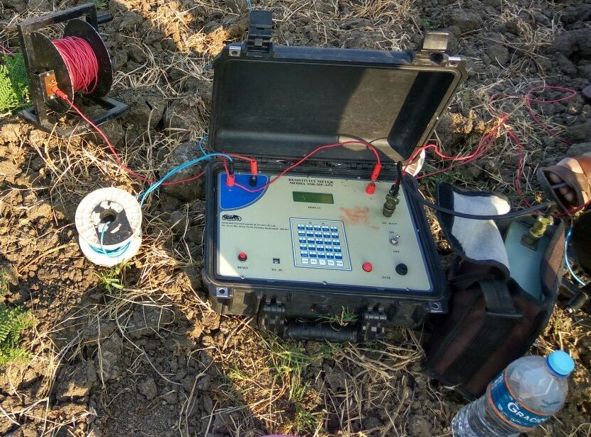
Reliable soil resistivity data requires professional-grade instruments operated by trained field engineers. At Bhoojal Survey, our field teams deploy:
- Soil resistivity meters (4-terminal earth testers) calibrated for precision measurement
- Stainless steel or copper-bonded electrodes for accurate current injection and voltage pickup
- GPS mapping tools for precise electrode location documentation and site mapping
- Data logging systems for real-time field recording and post-processing
- Geophysical survey instruments for deeper investigation and multi-layer analysis
Our teams are experienced in conducting hydrogeological survey using SSRMPATS Instrument, GER DETECT, and PQWT at site for open well / borewell location — extending our capability from surface resistivity analysis into deeper subsurface investigation.
We provide advanced groundwater survey and geophysical survey solutions that combine resistivity analysis with hydrogeological interpretation, giving clients a complete picture of subsurface conditions for both earthing design and groundwater assessment.
Factors Affecting Soil Resistivity
Resistivity is not a fixed property — it varies based on multiple site-specific factors:
- Moisture content: Wet soil conducts far better than dry soil. Resistivity can vary by an order of magnitude between monsoon and peak summer.
- Soil composition: Clay has low resistivity; sand and gravel have high resistivity. Rock is nearly non-conductive.
- Temperature: Resistivity increases as temperature drops, with frozen ground being an extreme case.
- Mineral concentration: Dissolved salts in soil moisture significantly lower resistivity. Highly saline soils are excellent conductors.
- Groundwater conditions: The presence of a shallow water table can dramatically reduce resistivity at depth.
- Seasonal changes: India's monsoon cycle creates significant seasonal resistivity variation that must be factored into earthing design.
Understanding these factors requires experienced interpretation — not just raw numbers.
Step-by-Step Soil Resistivity Test Procedure
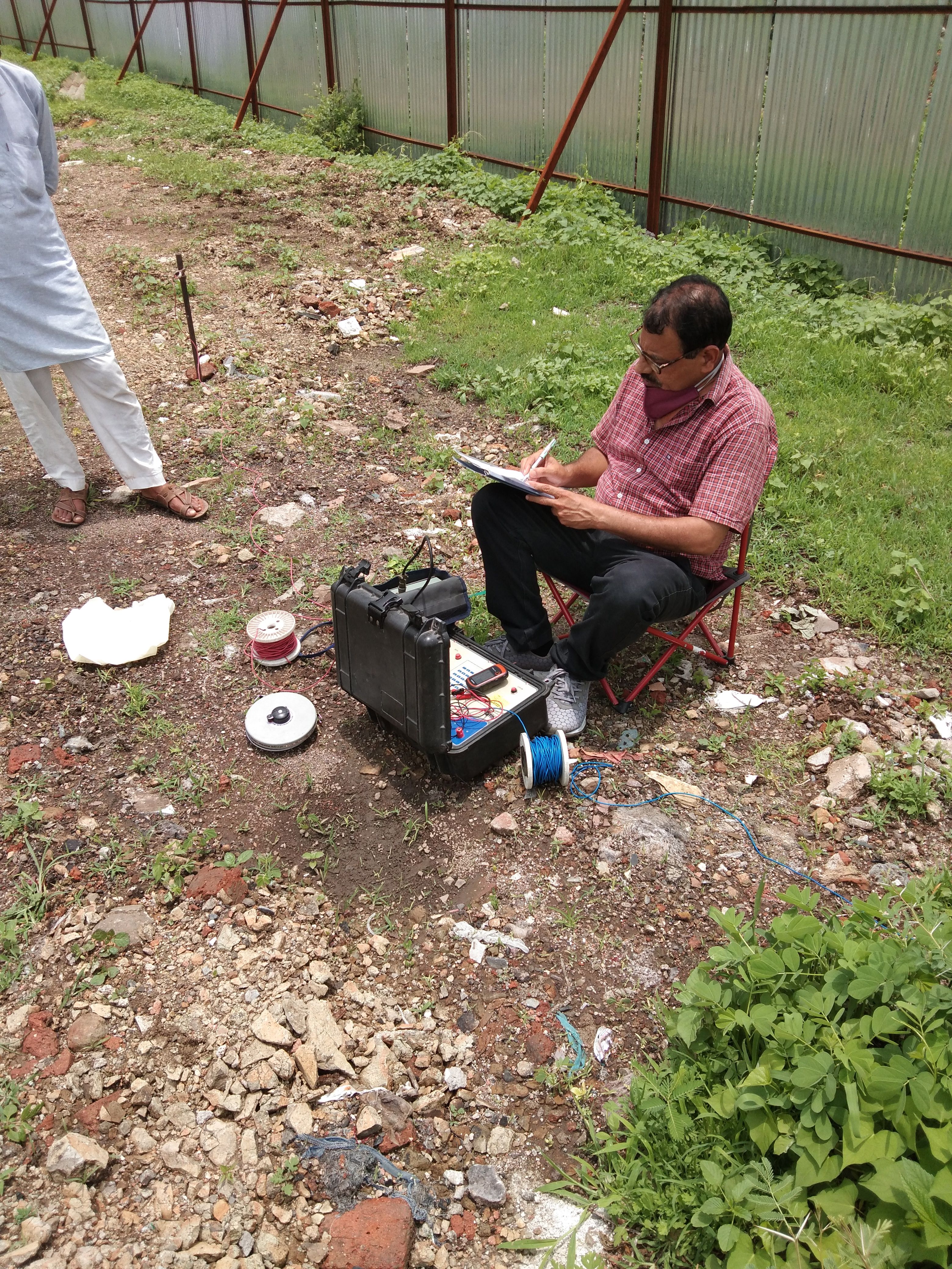
Our field teams follow a structured, quality-controlled testing workflow on every site:
- Site inspection: Assess terrain, access points, underground services, and safety conditions before any equipment is deployed.
- Survey planning: Determine electrode array orientations, spacing intervals, and measurement depths based on project requirements.
- Electrode placement: Drive electrodes at calculated positions, ensuring good soil contact for accurate readings.
- Current injection: Apply alternating current through the outer electrodes using the soil resistivity meter.
- Voltage measurement: Record the potential difference across the inner electrodes at each spacing interval.
- Field data collection: Log all readings systematically, noting ambient conditions, soil observations, and GPS coordinates.
- Resistivity calculation: Apply Wenner or relevant formula to compute apparent resistivity values at each measurement depth.
- Data interpretation: Analyze the resistivity profile to identify soil layers, anomalies, and depth-dependent behavior.
- Technical report preparation: Compile a structured report with measured data, interpreted profiles, and soil model parameters.
- Engineering recommendations: Provide specific earthing design guidance — electrode type, configuration, depth, and enhancement measures if required.
This systematic approach ensures every project receives data that is both technically defensible and practically actionable.
Benefits of Professional Soil Resistivity Testing Services
Investing in a proper soil resistivity survey before earthing design pays for itself many times over:
- Accurate earthing design: Right-sized systems — neither over-designed nor under-built.
- Cost savings: Avoid expensive rework when installed systems fail to meet resistance targets.
- Reduced project risk: Data-driven designs reduce the probability of electrical safety incidents.
- Better infrastructure planning: Soil data informs not just earthing but also cable laying, foundation design, and corrosion protection planning.
- Improved electrical safety: Compliant earthing protects workers, equipment, and the public throughout the project lifecycle.
- Reliable long-term performance: Designs based on accurate data continue to perform across seasonal and environmental variations.
For project owners and EPC contractors, professional soil investigation services are a small investment against the total project cost — with outsized returns in safety and performance.
Why Choose Bhoojal Survey
Bhoojal Survey is a specialized survey consultancy providing scientific site investigation and resistivity analysis services to infrastructure developers, government contractors, and industrial project owners across India.
Here is what distinguishes our service:
- Experienced technical team: Our field engineers have hands-on experience across solar plants, substations, industrial facilities, airports, and mining projects.
- Advanced survey instruments: We use calibrated, professional-grade equipment — not off-the-shelf testers — for results you can trust.
- Scientifically validated methodology: All testing follows recognized standards including IS:3043, IEEE 80, and IEC 62305.
- Comprehensive technical reporting: Our reports include raw data, interpreted soil models, and specific engineering recommendations — ready for use by your earthing design engineer.
- Fast turnaround: We understand project timelines. Our reporting process is efficient without compromising accuracy.
- Pan-India coverage: From Gujarat to Assam, from Rajasthan to Tamil Nadu — our teams operate across all major project geographies.
- Customized solutions: Every site is different. We adapt our survey approach to your specific project requirements, soil conditions, and design targets.
Whether you are developing a 100 MW solar park in Rajasthan, commissioning a 220 kV substation in Maharashtra, or building a data center in Bengaluru — Bhoojal Survey has the expertise and equipment to deliver the soil data your project needs.
Contact us today for a site assessment, quote, or technical consultation. Our team is ready to support your project from survey to report.
Conclusion
A soil resistivity test is not a regulatory formality — it is the engineering foundation on which every safe and effective earthing system is built. Accurate resistivity data protects infrastructure, people, and investment. It is indispensable for solar plants, substations, industrial facilities, and any project where electrical safety is a priority.
At Bhoojal Survey, we bring 15+ years of field experience, advanced instruments, and rigorous methodology to every soil resistivity survey. Our clients — EPC contractors, infrastructure developers, and project owners across India — rely on our data because they know it is accurate, interpreted by experts, and delivered when they need it.
If your next project requires professional soil resistivity testing, reach out to the Bhoojal Survey team today.
Frequently Asked Questions (FAQ)
What is a soil resistivity test? A soil resistivity test measures how much the soil resists electrical current flow. It is expressed in ohm-meters (Ω·m) and is used to design grounding and earthing systems for electrical infrastructure. Lower resistivity means better electrical conductivity.
Why is soil resistivity important for earthing design? Soil resistivity determines how efficiently electrical current — including fault currents and lightning energy — can be dissipated into the ground. Without this data, earthing systems cannot be sized correctly, leading to safety risks and potential system failures.
Which method is most commonly used for soil resistivity testing? The Wenner four-pin method is the most widely used technique. It is accurate, field-practical, and recognized by IS, IEEE, and IEC standards. For detailed subsurface profiling, the Schlumberger method is also used.
How long does a soil resistivity survey take? A standard survey for a medium-sized site (1–5 acres) typically takes one to two days including field testing and preliminary data processing. Final technical reports are usually delivered within 3–5 working days of field completion.
What industries require soil resistivity testing? Solar power plants, electrical substations, industrial facilities, airports, telecom towers, data centers, mining projects, railway infrastructure, commercial buildings, and government infrastructure projects all require soil resistivity testing before earthing system design.
Can soil resistivity values change over time? Yes. Resistivity varies seasonally with moisture content and temperature. Testing during multiple seasons, or designing for worst-case (high resistivity) conditions, ensures the earthing system performs reliably year-round.
What does a soil resistivity test report include? A professional report includes field measurement data, apparent resistivity at multiple depths, interpreted soil layer model, and specific engineering recommendations for earthing system design — ready for use by the project's electrical engineer.
Is soil resistivity testing mandatory for solar projects in India? While not always mandated by a single regulation, IS:3043 and IEEE 80 — the standards referenced by most solar EPC and substation projects — require earthing systems to be designed based on measured soil resistivity data. Most quality-conscious developers mandate it as part of their design process.